Wideband Overview
A wideband oxygen (O2) sensor is a crucial component for tuning and monitoring the air-fuel ratio (AFR) in an engine, especially when using an aftermarket Engine Control Unit (ECU). Unlike narrowband sensors, which only indicate whether the AFR is above or below stoichiometric (14.7:1 for gasoline), wideband sensors provide a precise measurement across a wide range of AFRs. This accuracy is essential for several reasons:
- Optimal Engine Performance:
- A wideband O2 sensor allows for fine-tuning of the AFR, ensuring the engine runs at its peak performance. This precise control helps achieve maximum power output and throttle response.
- Fuel Efficiency:
- By accurately measuring the AFR, a wideband sensor enables the ECU to adjust fuel delivery more precisely. This optimization leads to better fuel economy, reducing overall fuel consumption and operating costs.
- Engine Safety:
- Running an engine too lean (excess air) or too rich (excess fuel) can cause damage over time. A wideband sensor provides real-time data to the ECU, which can then make immediate adjustments to maintain a safe AFR, protecting engine components from damage such as knocking, overheating, or fouling.
- Tuning Flexibility:
- Aftermarket ECUs are often used in performance and custom applications where standard ECUs are insufficient. A wideband O2 sensor allows for extensive tuning flexibility, accommodating modifications such as forced induction, different fuel types, and various engine configurations.
- Diagnostic Capability:
- A wideband sensor can help diagnose issues quickly by providing detailed AFR data. This capability is invaluable for troubleshooting and ensuring the engine runs smoothly and efficiently.
In summary, integrating a wideband O2 sensor with an aftermarket ECU is essential for optimizing performance, enhancing fuel efficiency, ensuring engine safety, controlling emissions, and providing comprehensive diagnostic capabilities. It allows for precise control over the engine’s AFR, which is critical in any high-performance or custom tuning scenario.
Wideband Sensor Installation
The Sensor Cable Connector is the connection point between the sensor and the controller. Follow these steps for proper installation:
- Positioning of the Wideband Controller:
- Choose a permanent location for your wideband controller. Most users install the wideband controller alongside the ECU inside the cabin of the vehicle. Ensure this location is dry, protected from direct heat, and shielded from other external elements.
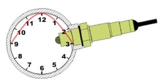
- Installing the Sensor:
- Install the sensor 24 inches downstream of the exhaust manifold collector or 24 inches after the turbo. Position the sensor between the 9 o’clock and 3 o’clock positions in the exhaust pipe (refer to the picture).
- This orientation helps prevent damage from condensation.

- Routing the Sensor Cable:
- Route the cable from the sensor through the car, avoiding direct heat sources
- Typically, this involves passing the cable through the firewall into the cabin of the vehicle. Use a firewall grommet or grommet plug to protect the cable, ensuring it is properly insulated and secured where it passes through the firewall to prevent chafing and potential damage.
- Once the cable is inside the cabin, connect it to the Sensor Cable Connector on the controller. With this connection made, the installation on this end is complete.
TunerStudio Project Setup
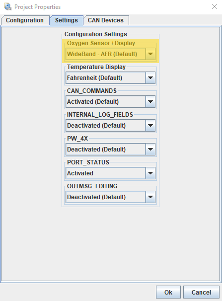
- Confirm your Oxygen Sensor is set to Wideband
- Go to Project Properties (Ctrl + P) or File > Vehicle Projects > Project Properties > Settings
- Confirm Oxygen Sensor / Display = Wideband – AFR (Default)

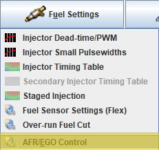
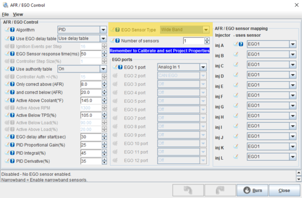
- Confirm AFR/EGO Control is set to Wideband
- Go to Fuel Settings > AFR/EGO Control > EGO Sensor Type

- Confirm EGO Sensor Type = Wide Band

- Go to Fuel Settings > AFR/EGO Control > EGO Sensor Type
Recommended Wiring
MS3Pro Based ECU
- Products included: MS3Pro Ultimate, MS3Pro Evo, MS3Pro MINI, and all MS3ProPNP Models
- Recommended Wiring:
- Wideband Power > Switched 12v
- Wideband Ground > MS3Pro High Current Out
- Reasoning:
- No risk of voltage offset as the wideband is grounded through the ECU
- Full control of Active Conditions to determine when the wideband is active
- Simplified wiring as there’s no need to tie into the fuel pump relay
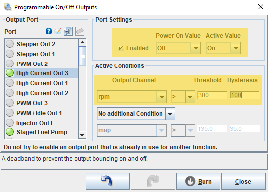
- Setup in TunerStudio:
- Advanced Engine > Programmable On/Off Outputs
- Port Settings: Enabled checked
- Power On Value = Off
- Active Value = On
- Active Conditions
- Output channel = rpm >
- Threshold / Hysteresis = 300 / 100

- Port Settings: Enabled checked
- Advanced Engine > Programmable On/Off Outputs
MS2 Based ECU
- Products included: Microsquirt and all MSPNP2 Models
- Recommended Wiring:
- Wideband Power: 12V Power to Fuel Pump Relay
- Wideband Ground: Use to the same location as the ECU Ground
- Reasoning: this avoids powering the O2 sensor without the engine running preventing potential damage from condensation shock-cooling a hot sensor. This allows the engine and sensor to warm up together.
Innovate LC-2 Installation
Wiring Instructions
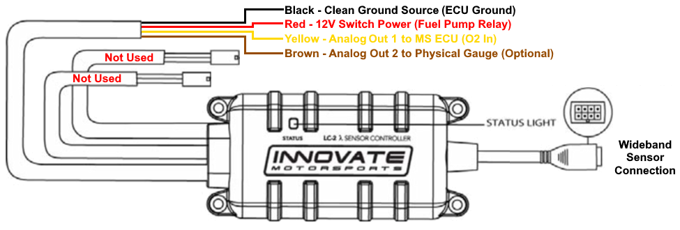
- Red Wire
- Function: Power to the Wideband
- Connection: Connect to a 12V Switched Power Source protected by a 5A fuse
- Recommended Source: see “Recommended Wiring” Section
- Reasoning: this avoids powering the O2 sensor without the engine running preventing potential damage from condensation shock-cooling a hot sensor. This allows the engine and sensor to warm up together.
- Black Wire
- Function: Ground to the Wideband
- Connection: Connect to a reliable and clean ground source
- Recommended Source: see “Recommended Wiring” Section
- Yellow Wire
- Function: Analog Out 1
- Connection:
- MS3Pro Evo – Connect to “O2 In” Pin 25 (Pink Wire)
- MS3Pro Mini – Connect to “Analog in 1” Pin 13 (Lt Blue/Blue Wire)
- Microsquirt – Connect to “O2” Pin 34 (Pink Wire)
- MS3Pro PNP – Confirm with your ECU’s documentation for the correct input
- MSPNP2 – Confirm with your ECU’s documentation for the correct input
- Brown Wire (Optional)
- Function: Analog Out 2
- Connection: Connect to an input on a physical gauge or any other external logger that accepts a 0-5V signal. IF NOT USED, clip bare wires and properly cover with electrical tape for safety.
- NOTE: By default, Analog Out 2 is set up for narrowband. You will need to use the LM Programmer to configure it for wideband. Please refer to the LC-2 Manual for detailed steps by making Analog Out 1 values the same on Analog Out 2.
TunerStudio Configuration
The next step is calibrating your Wideband Controller in TunerStudio. It’s crucial to ensure that your Wideband signal outputs the correct reading to your ECU. Each controller has its own output range, so their calibrations are not identical.
- Open TunerStudio on your tuning laptop
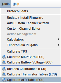
- Unlock Calibration Tables
- Go to Tools > Un/Lock Calibrations, then set Sensor Calibrations to “Unlocked”
- Calibrate your Wideband to your ECU
- Go to Tools > Calibrate AFR Table

- Go to Tools > Calibrate AFR Table
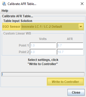
-
- Choose from the EGO Sensor dropdown menu “Innovate LC-1 / LC-2 Default”
- Click on the button “Write to Controller”
- Once the calibration has been updated, click on the Close button

AEM X-Series Installation

Wiring Instructions
- Red Wire
- Function: Power to the Wideband
- Connection: Connect to a 12V Switched Power Source protected by a 5A fuse
- Recommended Source: see “Recommended Wiring” Section
- Reasoning: this avoids powering the O2 sensor without the engine running preventing potential damage from condensation shock-cooling a hot sensor. This allows the engine and sensor to warm up together.
- Black Wire
- Function: Ground to the Wideband
- Connection: Connect to a reliable and clean ground source
- Recommended Source: see “Recommended Wiring” Section
ONLY Choose One Connection Method to your ECU
Analog Connection
-
- White Wire
- Function: Analog (+)
- Connection:
- MS3Pro Evo – Connect to “O2 In” Pin 25 (Pink Wire)
- MS3Pro Mini – Connect to “Analog in 1” Pin 13 (Lt Blue/Blue Wire)
- Microsquirt – Connect to “O2” Pin 34 (Pink Wire)
- MS3Pro PNP – Confirm with your ECU’s documentation for the correct input
- MSPNP2 – Confirm with your ECU’s documentation for the correct input
- Brown Wire
- Function: Analog (-)
- Connection: Connect to an available Sensor Ground based on ECU type
- Wire-In ECU: available within the harness, please refer to the ECU’s wiring diagram
- PNP Models: available on the Options Port, please refer to the ECU’s wiring diagram
- White Wire
CanBus Connection
-
- Can L: Connect to the Can L wire on your ECU
- Can H: Connect to the Can H wire on your ECU
- NOTE: The X-Series Controller does not have an internal terminating resistor. Therefore, you will need to add a 120 Ohm resistor for a properly terminated network.
TunerStudio Configuration
The next step is calibrating your Wideband Controller in TunerStudio. It’s crucial to ensure that your Wideband signal outputs the correct reading to your ECU. Each controller has its own output range, so their calibrations are not identical.
Analog Connection
- Open TunerStudio on your tuning laptop
- Unlock Calibration Tables
- Go to Tools > Un/Lock Calibrations, then set Sensor Calibrations to “Unlocked”
- Calibrate your Wideband to your ECU
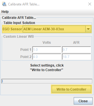
- Go to Tools > Calibrate AFR Table
- Go to Tools > Calibrate AFR Table
-
- Choose from the EGO Sensor dropdown menu “AEM Linear AEM-30-03xx”
- Click on the button “Write to Controller”
- Once the calibration has been updated, click on the Close button

CanBus Connection
Note: AEM uses the standard 29-bit CAN protocol, which is not the same as the Megasquirt Extended 29-bit protocol. This means you can NOT connect any additional Megasquirt CAN devices (e.g., DD-EFI Digital Dash, Transmission Controller, I/O Module) while the AEM X-Series Controller is connected via this CANbus connection.
- Open TunerStudio on your tuning laptop
- Calibrate your Wideband to your ECU
- Go to CAN-bus/Testmodes > CAN EGO, GPS

- Go to CAN-bus/Testmodes > CAN EGO, GPS
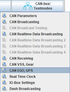
-
- Choose from the Fetch EGO Data dropdown menu “AEMX UEGO”
- Click on the Burn button at the bottom of the screen


Spartan 3 Installation

Wiring Instructions
- Terminal #1 – Electronics Power
- Function: Power to the Controller
- Connection: Connect to a 12V Switched Power Source protected by a 5A fuse
- Recommended Source: see “Recommended Wiring” Section
- Reasoning: this avoids powering the O2 sensor without the engine running, preventing potential damage from condensation shock-cooling a hot sensor. This allows the engine and sensor to warm up together.
- Terminal #2 – Electronics Ground
- Function: Ground to the Controller
- Connection: Connect to a reliable and clean ground source
- Recommended Source: see “Recommended Wiring” Section
- Terminal #3 – LSU Heater Power
- Function: Power to the Wideband
- Connection: Connect to a 12V Switched Power Source protected by a 5A fuse
- Recommended Source: Connect to the same source as Terminal #1
- Reasoning: this avoids powering the O2 sensor without the engine running, preventing potential damage from condensation shock-cooling a hot sensor. This allows the engine and sensor to warm up together.
- Terminal #4 – LSU Heater Ground
- Function: Ground to the Wideband
- Connection: Connect to a reliable and clean ground source
- Recommended Source: Connect to the same source as Terminal #2
ONLY Choose One Connection Method to your ECU
Analog Connection
- Terminal #6 – High Perf Linear Output
- Function: Wideband Analog Output
- Connection:
- MS3Pro Evo – Connect to “O2 In” Pin 25 (Pink Wire)
- MS3Pro Mini – Connect to “Analog in 1” Pin 13 (Lt Blue/Blue Wire)
- Microsquirt – Connect to “O2” Pin 34 (Pink Wire)
- MS3Pro PNP – Confirm with your ECU’s documentation for the correct input
- MSPNP2 – Confirm with your ECU’s documentation for the correct input
CanBus Connection
- Terminal #7 – Can High: Connect to the Can H wire on your ECU
- Terminal #8 – Can Low: Connect to the Can L wire on your ECU
NOTE: The Spartan 3 Controller by default has the termination resistor ENABLED
TunerStudio Configuration
The next step is calibrating your Wideband Controller in TunerStudio. It’s crucial to ensure that your Wideband signal outputs the correct reading to your ECU. Each controller has its own output range, so their calibrations are not identical.
Analog Connection
- Open TunerStudio on your tuning laptop
- Unlock Calibration Tables
- Go to Tools > Un/Lock Calibrations, then set Sensor Calibrations to “Unlocked”
- Calibrate your Wideband to your ECU
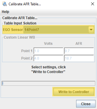
- Go to Tools > Calibrate AFR Table
- Go to Tools > Calibrate AFR Table
-
- Choose from the EGO Sensor dropdown menu “AEM Linear AEM-30-03xx”
- Click on the button “Write to Controller”
- Once the calibration has been updated, click on the Close button

CanBus Connection
NOTE: Needs to use firmware 1.6.xxx
- Open TunerStudio on your tuning laptop
- Calibrate your Wideband to your ECU
- Go to CAN-bus/Testmodes > CAN EGO, GPS
- Go to CAN-bus/Testmodes > CAN EGO, GPS
-
- Choose from the Fetch EGO Data dropdown menu “14point7 Spartan 3”
- Click on the Burn button at the bottom of the screen

